|
Download Members: $0.00 Non‑Members: $75.00 |
Buy Now |
Publication Details
| Published Date: | |
|---|---|
| Authors: | Scott Waltari, Edward Sergoyan, Scott Sandwith |
| Company: | CMSC |
| Print Format: | Technical Paper |
| Citation: | Scott Waltari, Edward Sergoyan, Scott Sandwith, "Wing Interior Structure Measurement Solution: Rotating Laser Scanner–Tracker Integration," The Journal of the CMSC, Vol. 3, No. 2, Autumn 2008 |
Abstract
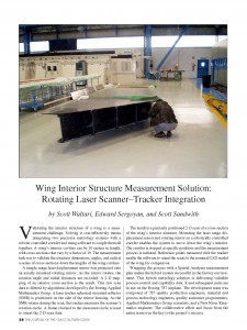
Validating the interior structure of a wing is a measurement challenge. Solving it cost-effectively meant integrating two precision metrology systems with a robotic controlled crawler and using software to couple them all together. A wing’s interior cavities can be 10 m in length with cross-sections that vary by a factor of 10. The measurement task was to validate the structure dimensions, angles, and radii at a series of cross-sections down the lengths of the wing cavities. A simple range laser displacement sensor was projected onto an axially-mounted rotating mirror. As the mirror rotates the rotation angle and radial distances are recorded. A 2D mapping of an interior cross-section is the result. This raw scan data is filtered by algorithms developed by the Boeing Applied Mathematics Group. A laser tracker spherical mounted reflector (SMR) is positioned on the side of the mirror housing. As the SMR rotates during the scan, the tracker measures the scanner’s rotation circle. A frame clocked to the measured circle is used to orient the 2D scan data. The result is a precisely positioned 2D scan of a cross-section of the wing’s interior structure. Mounting the laser range displacement sensor and rotating mirror on a robotically controller crawler enables the system to move down the wing’s interior. The crawler is stopped at specific positions and the measurement process is initiated. Reference points measured with the tracker enable the software to orient the scans to the nominal CAD model of the wing for comparison. Wrapping the process with a SpatialAnalyzer Measurement Plan (MP) makes the hybrid system successful in the factory environment. This hybrid metrology solution is delivering valuable process control and capability data. It and subsequent units are in use on the Boeing 787 aircraft. The development team was composed of quality production engineers, M&PT engineers, quality assurance programmers, Applied Mathematics Group scientists and a New River Kinematics engineer. The collaborative effort and focus from the entire team was the key to the project’s success.


